JOB VACANCY: CNC MACHINIST
Phone: 01484 556288

OUR EXCEPTIONAL GEAR CUTTING SERVICES
Precision hobbing, shaping, milling and grinding of a wide variety of gears
Our precision gear cutting service is aimed at businesses large and small and our skilled engineers are experienced in working on a wide variety of gear types. No matter how simple or how complex the job, you can be assured of first class work and rapid service from the team at Westin Engineering.
Creating bespoke components – or reverse engineering new parts from old ones or drawings – is part of our daily work. Our customers come from across the spectrum of industries, among them textiles, mining and quarries, chemical, oil and gas, water, power generation and food and drink.
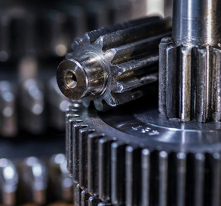
SPUR GEARS
These are a common gear type and among the most cost effective methods of gearing. Generally they have straight teeth and transmit motion and power between parallel shafts.
HELICAL GEARS
Helical are similar to spur gears except the teeth are cut at an angle to the axis. They typically engage more slowly and smoothly than other types of gears because the load is transferred uniformly and gradually.
INTERNAL GEARS
Also known as ring gears, these are similar to external spur gears except the teeth are cut into the inside diameter while the outside remains smooth. They can bring speed reductions and reduced sliding wear in a range of applications.
BEVEL GEARS
We custom manufacture high quality bevel gears for many industries, from small to large, in a variety of materials and size ranges.
WORMS and WORM WHEELS
We create custom engineered and standard worms for particular gearing applications. We can make single or multiple start worms with right or left hand threads and/or multiple leads.

The range of gear cutting services at Westin Engineering
-
Gear manufacturing
-
Gear hobbing
-
Gear shaping
-
Gear milling
-
Gear profiling
-
Gear grinding
-
Spur gears
-
Helical gears
-
Internal gears
-
Gear clusters
-
Partial gears
-
Gear quadrants
-
Bevel gears
-
Ring gears
-
Sprockets
-
Split gears
-
Gear couplings
Gears and gear teeth exist in infinite varieties, so it’s difficult to cover all eventualities. So if you have any questions about gear manufacturing or precision engineering, please speak to one of our friendly team.
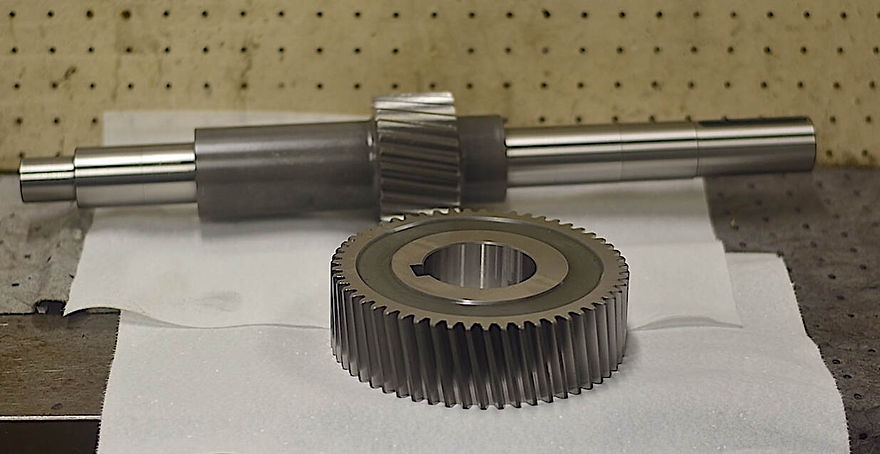
The process begins on the lathe, where the steel (EN36) is turned down to a precise size to allow for grinding where required on the two parts. This means that when the parts come back from hardening, they can be ground between centres. The keyways are then milled into the pinion using our Bridgeport miller or XYZ millers.
The pinion is set up and cut on our David Brown hobber (for helical gears) or on one of our Jowett’s (for spur gears). For this job, it was on the David Brown. Meanwhile, the wheel is set up and cut on the Sunderland gear planer which does both helical and spur gears. In this process we cut to given or calculated sizes and allow for grinding. We are one of the few companies that still dress gears by hand, giving them a better appearance and fewer sharp corners.
After the pinion has come back from hardening, it is ground between centres on our Churchill OD and Bore grinder. The wheel is bore ground on the Churchill grinder and then face ground, making sure the face is true to the bore. The other face is then ground on our various surface grinders. Finally, the pinion is set up between centres on the Niles gear grinder and ground.
The gear and pinion go through several hands during this process, so accuracy at each stage is vital. Our skilled, experienced engineers ensure the job is successfully completed to the highest quality and ready to be securely packed and sent to the customer.